Split Receptacle Wiring Diagram
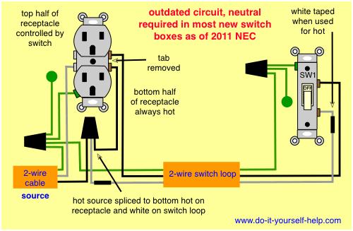
The long slot on the left is the neutral contact and the short slot is the hot contact. Turn the power off before starting this or any wiring project.

Wiring Diagram 3 Way Switch Split Receptacle Database
Wire just like you do with a light (almost) at switch (a) bring power.

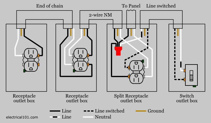
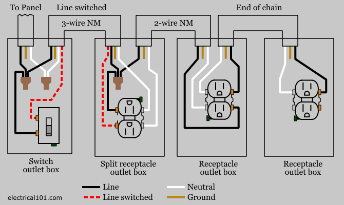
Split receptacle wiring diagram. The source neutral is connected to one of the neutral terminals on the receptacle. Kitchen split receptacle circuit wiring diagram: For split receptacle wiring, you will need to use 14/3 or 12/3 wire.
Connect the white to the common terminal. 32 us galh 12lh max. Connect the black to the bottom and the red to the top hot side.
Alternate split receptacle wiring diagram. Switched split outlet wiring diagram for controlling the half of two duplex electrical receptacles by a wall switch without a neutral conductor. The tab connecting the hot terminals on the receptacle is removed and the source hot is connected to the bottom half.
Switched split receptacle basic electrical wiring, home. So if you are using a toaster plugged into the top half, and it is using 8a on circuit #1, and the coffee maker plugged into the bottom half using 6 amps, then the neutral will only be carrying 2 amps of current back to the panel. A split receptacle also requires a 2 pole breaker.
Combination switch receptacle wiring diagram wiring. A split receptacle has one or both tabs removed to isolate each terminal from the. Solesus air 115 volt evaporators.
Wiring diagrams to add a new receptacle outlet wiring diagram receptacle to switch to light fixture in wiring diagrams for switched wall outlets before reading the schematic get common and understand all the symbols. In the wiring diagram below the white wire that goes to the switch is being used as the hot conductor, not as a neutral. Mini split condensate pump wiring diagram.
This style of breaker enables the receptacle to have. When wiring a split receptacle this way, use the quick connect holes at the back of the plug or pigtail the wires to the side screws. Switched split receptacle wiring diagrams.
For split receptacle wiring, you will need to use 14/3 or 12/3 wire. The diagram shows the power entering into the circuit at the switch box location then sending one power line for the outlet which is hot all the time and a switched leg for the top half of the outlet being used for a table lamp or a floor. Mini split condensate pump wiring diagram wiring diagram.
Do you know the thought of clear vue mini wiring diagram we present to you in this posting relates to the demand report about clear vue mini wiring diagram. 12 3 wiring switched outlet diagram. The black wire (line) connects to half of the split receptacle (always hot) and two other nm cables.
Alternate split receptacle wiring diagram. Split recepticle wiring electrical 101 an afci outlet with gfci receptacles kitchen receptacle circuits how to install in this situation 31 common household circuit wirings you adding outlets and switch after gcfi diagram for 20a gfi wire back wired connections. Wiring diagram for two switches to control one receptacle.
Because the two circuits are from opposite sides of the panel, the neutral will only carry the unbalance load. Although cheaper, it is not a good way to get a new hairstyle. It has the same wires as the regular plug but now there is a red wire in the mix.
Switch controls multiple receptacles home electrical wiring. You can also branch off an existing split receptacle by simply matching colors to the existing plug. 3 when using split downstream receptacle, ensure the connecting link is broken to enable independent line/hot and switched line/hot.
Here is a basic electrical wiring diagram that shows how to add multiple receptacles. Read or download way split receptacle for free wire diagram at skywiringzeropixelfestivalit. Wiring a switch an outlet electrical switches, outlet.
Run a 3 wire to switch (b). This diagram illustrates the wiring for a split half outlet controlled with a switch loop. Wiring diagrams to add a new receptacle outlet.
The black wire carries line to the always hot half of the split receptacle. Collection of electrical receptacle wiring diagram. 2 downstream receptacles are optional.
Now break the tap between the two screw. It has the same wires as the regular plug but now there is a red wire in the mix. Gfci wiring with unprotected switch and light diy and.
Wiring multiple outlets in a series in this diagram wall outlets are wired in a row using the terminal screws to pass voltage from one receptacle to the next. From switch (a) run another 3 wire to the split receptacle. Combo plug and light switch wiring electrical question.
One duplex receptacle split to be controlled by 2 switches diy home improvement forum. Wiring a split switched outlet with a switch loop. A duplex receptacle has removable metal tabs that electrically connect the two terminals together on each side of the receptacle.
With easy to follow diagrams and instructions you can have that convenience in no time.

Electrical Outlet Split Circuit Wiring Top Latest Multiple Gfci Outlet Wiring Diagram Diagrams
Wiring Diagram 3, Switch Split Receptacle Best House Light Wiring Diagram Uk 3, Switch Split


Wiring a Split, Switched Receptacle. Home electrical wiring, Electricity, Switch

Wiring Diagram Split Receptacle Wiring Diagram
Wiring A Split Switched Outlet Cleaver Latest Wiring Diagram 3, Switch Split Receptacle, Do I Go

Wiring Diagram 3, Switch Split Receptacle Professional Split Circuit Receptacle Unique 3, Switch


Switched Split Outlet Wiring Diagrams Mr. Electrician Outlet wiring, Wiring diagram, Light
Split Recepticle Wiring Electrical 101

One Duplex Receptacle Split To Be Controlled By 2 Switches Electrical DIY Chatroom Home

split switched outlet wiring diagram Basic electrical wiring, Home electrical wiring, Outlet
Light Switch Wiring Diagrams

Switched Split Outlet Wiring Diagrams Mr. Electrician Outlet wiring, Switch, Circuit breaker

AZ DIY Guy's Projects Wiring a split, switched receptacle.
Gfci Split Receptacle Wiring Diagram Perfect Gfci Split Receptacle Wiring Diagram Switched


1 Split Receptacle With 2 Switches Electrical DIY Chatroom Home Improvement Forum
How To Wire A Switch Ground Perfect Diagram Switched Split Receptacle Wiring Switch Lights

Split Recepticle Wiring Electrical 101
Wiring A Split Switched Outlet Top Wiring Diagram, To Wire A Split Receptacle Controlled By At 3

15 Top Gfci Split Receptacle Wiring Diagram Images Tone Tastic
