Engine Hour Meter Wiring Diagram
* the quartz hour meter is specially designed for standard industrial timing and supplying data for the reference of maintenance duration for precision equipment. Diagram c illustrates the time setting function.
Book Info Ac Hour Meter Wiring Diagram

Opposite terminal to neutral wire.

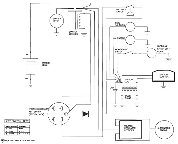
Engine hour meter wiring diagram. Connect a wire from pin #5 to a constant +12 or +24 volt source. Attach the wire from pin #3 to a ground (negative) source. You cannot hook it to the coil because that is a pulsed signal.
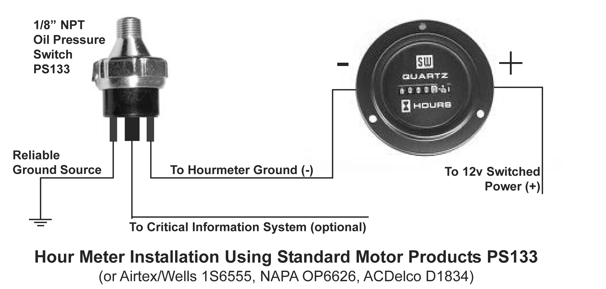
Single phase, 3 wire, /v system. Backlight total time product installation tach/maintenance/hour meter wiring diagram specifications features Their diagram makes the engine oil pressure switch appear to be dedicated solely for the engine hour meter.
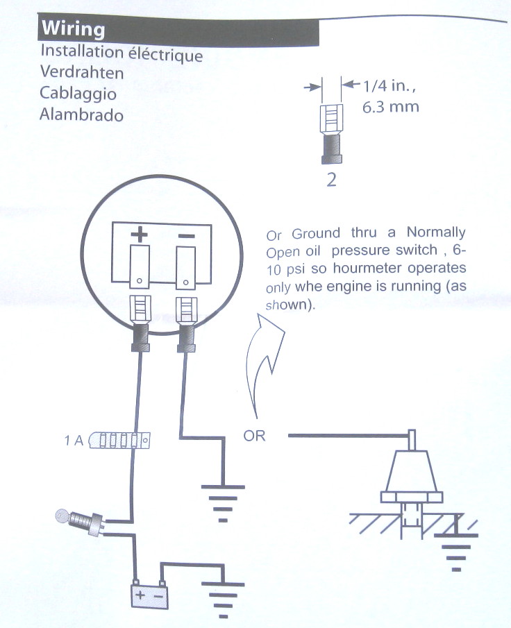
Can you simply just connect this ground wire from the hour meter to the oil pressure switch that already has a wire coming off of it and going to the engine oil pressure dummy light. [7 in the wiring diagram] “on mine the 12v lead had an eye and was on a stud with a nut, so i cut off the eye and put both leads in 1 eye, it’s working perfect.” Run wires from the quartz clock location through the firewall to:
Wiring the engine hour meter: Do this by connecting the wire to another ground wire with a scotch lock, or connecting it to a. The operation of the tach/hour meter is triggered by 5.5 ft.
Your hour meter will now keep time when the key is in under the hood (3/8” wrench). Viewline 52mm wiring diagram (2014) viewline standard resistive gauges 52mm installation sheet (2014) viewline temperature gauges 12/24 volt (2011) viewline temperature gauges 52mm (2008) Erly with your engine, you will need to set the switches as shown in diagrams c or d.
One such source can always be found where the battery is attached to the metal frame of the vehicle. The unit is powered by an internal cr2450 lithium battery, no external power connections are required. Connect the hot wire (usually red) on the back of the hour meter to the run wire on the back of the ignition switch, using a scotch lock wire connector.
Replace d away from steering shaft and shifter controls with provided zip ties. Opposite terminal to neutral wire. The wiring diagram does show a switched positive feed to the engine via the main wiring harness ( pin 3 on the multiway connector) but nothing on the engine is connected to it so probably not feasible to connect up in the engine bay.
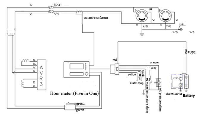
From this recorded data, you can monitor an operator's working hours, equipment usage time for future maintenance intervention, and other needs. Veratron flex gauge 52mm nmea2000 12/24v. Connect power wire to one terminal and neutral wire to opposite terminal.
Systems like these are made using equipment called an hour meter. Attach the wire from pin #8 to the positive (+) The hour meter is a piece of equipment that records the start and end times of an event.
Use an appropriate connector to ground this wire. This tach/maintenance/hour meter will keep track of true engine rpm and running time for most of 2/4 stroke gasoline engines. Erly with your engine, you will need to set the switches as shown in diagrams c or d.
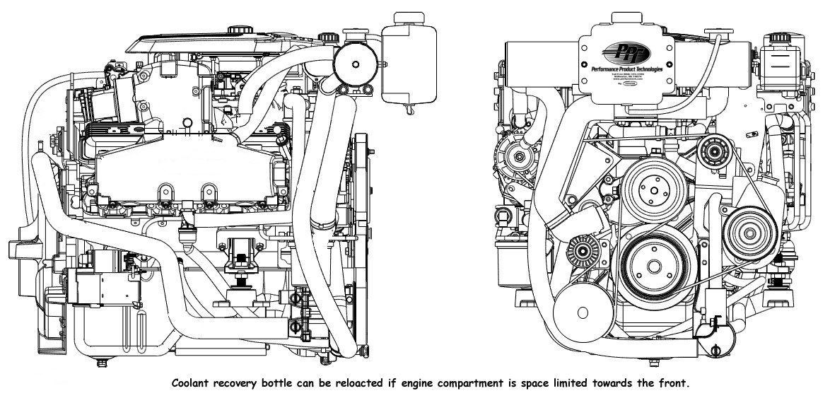
Connect the receptacle of the wire from the power source (step 5) to the hour meter’s B) the light switch (also after the fuse in the fuse box); Mercruiser l wiring diagram at performance product technologies/ schematron.org main menuservice manual number 26 marine engines gm 4 cylinder use care during the first 20 hours of operation on new mercruiser engines or the voltage in the ohm's position can be checked by using a second meter or.
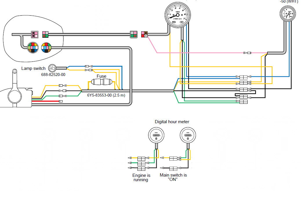
Most commonly, people connect the leads coming out of the hour meter to the electric fuel pump, which is designed to supply enough fuel to the injector pump. Cummins marine engine parts catalogs; When engine is on, the dispaly will read rpm of engine.
A) the positive (+) terminal on the ignition switch (after the fuse box); Attach the ground wire (usually black) on the back of the meter to the boat's grounding system. The hour meters are series wiring diagrams single phase, 2 wire, v system:
I’ve had my boat for 2 years, neither hour meter has changed since the sea trial, and i was thinking it was a disconnected wire running from the key to the tach…but the tach has a bunch of modular. The unit is widely used for tracking engine hours and will allow you to keep track. In this article, i will teach you exactly how.
When engine is off, the display will switch to total running time and remains visible. A) the positive (+) terminal on the battery (after the fuse box, but before the ignition switch or any other switch. The wiring diagram is in the owners manual available on line.
Shielded and external lead, wrapped around the spark plug Connect the provided wires as shown at right. Diagram d proper wiring of the vdo quartz clock diagram e wiring examples of the vdo engine hour meter wiring the quartz clock:
Red on left, black on right. You cannot hook it to the tach as the s terminal is also pulsed and besides, it is nowhere. From bayview, idaho, sails a 1989 hunter 30 sail boat.when he added an hour meter to his 2gm20 he pulled the 12v line from the oil pressure sending unit.
Run wire from the engine hour meter location through the firewall to:
Engine Hour Meter Wiring Diagram Wiring Diagram
Yamaha Digital Hour Meter Installation Help The Hull Truth Boating and Fishing Forum
Engine Hour Meter Wiring Diagram Wiring Diagram

Hour Meter Wiring Diagram Wiring Diagram

Hobbs Hour Meter 12v Wiring Diagram Wiring Diagram and Schematic

Hour Meter Wiring Diagram Wiring Diagram
Mercruiser 3.0 Engine Wiring Diagram For Hour Meter

Hobbs Hour Meter 12v Wiring Diagram Style Guru Fashion, Glitz, Glamour, Style unplugged
Engine Hour Meter Wiring Diagram Wiring Diagram

Hobbs Hour Meter 12v Wiring Diagram Style Guru Fashion, Glitz, Glamour, Style unplugged
Hour Meter Wiring Diagram Wiring Diagram

Hour Meters Page 1 iboats Boating Forums 10209792
Hobbs Hour Meter Wiring Diagram 20

Hour Meter Wiring Diagram Wiring Diagram
Engine Hour Meter Wiring Diagram Wiring Diagram
Hour Meter Wiring Diagram Wiring Diagram
Hobbs Hour Meter Wiring Diagram

CruzPro VAH60 Digital Volts Amp Hour Monitor VAH60R VAH60S e Marine Systems
Engine Hour Meter Wiring Diagram Wiring Diagram
